Kelsey Brake Controller Wiring Diagram

17 Kelsey Electric Brake Controller Wiring Diagram Wiring
Brake Controller Wire Functions By Wire Color Etrailer Com

E Scooter Wiring Diagram Electric Scooter Outlet With Images

E Scooter Wiring Diagram Wiringimage Us With Images Electric

Door Lock Actuator Wiring Diagram Wellread Me And Power Door

Typical Trailer Wiring Diagramcircuit Schematic With Images
To be safe i would suggest using a circuit tester such as part 40376 to verify the connections.
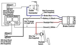
Kelsey brake controller wiring diagram. I have a kelsey energizer brake controller the wires aint mark what goes to what i have a blue one to the right i have attached a picture of a diagram of how brake controllers wire to tow vehicles. Bench testing a draw tite activator ii time delay brake controller. The kelsey trailer brake controller works only in 12 volt vehicles and on single and twin axle trailers. It cannot operate more than four electric brakes.
For vehicles without a trailer towing package. The black wire connects to the battery positive terminal through a circuit breaker to deliver operating power to the controller. The four wires on trailer brake controllers are standardized so they always connect in the same way. I need wiring instructions for kelsey brake controler model 10958001 i had this controller on a 1993 ford f 159 but sold the truck and took the controller off.
I have lost the owner manuel and i need to use the controller on a 2009 f 150. Installing a kelsey energize brake controller in your vehicle will provide power for your trailer s electric brakes. The trailer brake circuit or the white ground wire is not connected to ground. For vehicles without a trailer towing package.
And the red wire connects to the cold side of the brake. Refer to the wiring diagram in figure 4. If the stop lamps do not illuminate check the red stoplight wire connection of the brake controller for connections to the non powered stop lamp wire of the vehicle stop lamp switch. The blue wire carries the controller s output to the vehicle s trailer connector.
Without wiring the controller plug in the harness. Check and or repair wiring and tow vehicle trailer connector. The red controller wire must be connected to the light green wire of the brake. The white wire is ground.
Vehicle mechanical 20a blue trailer ground figure 4 wiring diagram warning. In 2011 kelsey currently produces in cab electronic brake controllers which have a similar set up to that of any other manufacturer s controllers. The 1156 light bulb simulates the trailer brakes and changes in brightness based on the brake controller output. All 1999 and later ford vehicles without the trailer wiring package.
Refer to the wiring diagram in figure 4. To the right i have attached a picture of a diagram of how brake controllers wire to tow vehicles.

16 Briggs And Stratton Vanguard Engine Wiring Diagram Engine

Razor Wiring Diagram Electric Scooter Razor Electric Scooter

Vs 6453 Electric Brake Box Wiring Diagram Download Diagram

At 9560 Hayes Brake Controller Wiring Diagram Schematic Wiring

10 E36 Engine Wiring Harness Diagram Engine Diagram In 2020

16 94 Chevy Truck Stereo Wiring Diagram Truck Diagram In 2020

91 F350 7 3 Alternator Wiring Diagram Regulator Alternator

Wiring Diagram Switch Loop Ceiling Fan With Images Ceiling
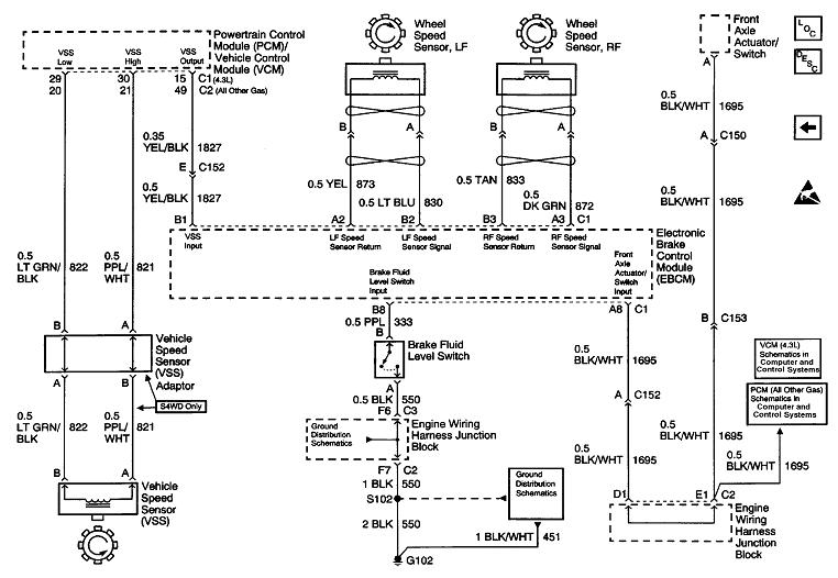
Abs Module Wiring The Protective Tubing On My Abs Module Wiring

Western Golf Cart Battery Wiring Diagram Within Ez Go With Images

Hayes Brake Controller Wiring Diagram Wiring Diagram

7 3 Powerstroke Glow Plug Relay Wiring Diagram Wildness Me

Nissan Titan Stereo Wiring Diagram Wiring Diagram
