Peterbilt Fan Clutch Wiring Diagram

Related Image Diagrama De Circuito Electrico Camiones

15 1998 Lincoln Town Car Wiring Diagram Car Diagram In 2020

Pin On Ceiling Fan Wiring Diagram

Nissan Leaf Battery Wiring Diagram Vauxhall Insignia Nissan

Hunter Universal Fan Remote Wiring With Images Ceiling Fan

Pin De Samuel Trejo En Diagrams Diagrama De Circuito Electrico
Lvd v out lvd v in wht0710 10 wht1500 fb8c spare power conn fb1 spare batt pwr f1b 1 f2b 1 f3b 1 f4b 1 f5b 1 f6b 1.
Peterbilt fan clutch wiring diagram. Peterbilt 348 schematics wiring diagram pdf. The ecm turn the fan off by sending out 12 volts on pin 11. Model 579 567 engine aftertreatment systems 2017 french. Engine fan harness door harness schematic 379 model family electrical p94 6023 c 02.
If the status of the fan is on the ecm is detecting something that makes it want to turn the fan on. When the ecm wants to turn the fan on it removes the 12 volts from pin 11. Keep hands and tools clear of the fan blades. A wiring diagram is a streamlined traditional photographic depiction of an electrical circuit.
It shows the elements of the circuit as simplified shapes as well as the power and signal links between the tools. Scale 1 8 fuse block j1587 data bus connector relay assembly. Collection of peterbilt 389 wiring schematic. The fan clutch can engage without warning.
Need a wiring diagram for a 1990 ls 400 need a wiring diagram for a 1990 ls 400. Repeat steps 1 3 for the n o. Install a jumper wire between the terminals of the n o. 1 52 mb pdf.
I have an 02 peterbilt 379 with c15 cat engine fan clutch started running continuously could you send me a wiring answered by a verified technician we use cookies to give you the best possible experience on our website. Model 579 567 engine aftertreatment systems 2017 french. Peterbilt 335 with 3126e schematics wiring diagram pdf. Set the manual.
Need wiring diagram peterbilt 379 fan clutch. Thermal switch this will engage the fan clutch.

Single Phase Forward Reverse Motor Wiring Diagram 1 With Images

Delphi Radio Wiring Diagram Diagram

10 Cummins Ism Engine Wiring Diagram Engine Diagram In 2020

16 Bus Electrical Wiring Diagram Wiring Diagram In 2020

Pin On Shaa Alroo

3 Wire Alternator Wiring Diagrams Google Search With Images

Nissan Leaf Battery Wiring Diagram Vauxhall Insignia Nissan
Va Trinary Switch Wiring

1964 Impala Wiring Diagram Wiring Diagrams With Images Impala
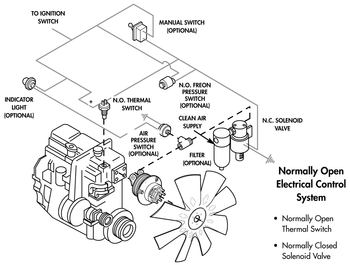
Selecting Proper Fan Drive Controls

Soarer Ecu Pinout Dengan Gambar Mobil Teknologi

2001 Gmc Sierra Wiring Diagrams With Images Chevy Silverado
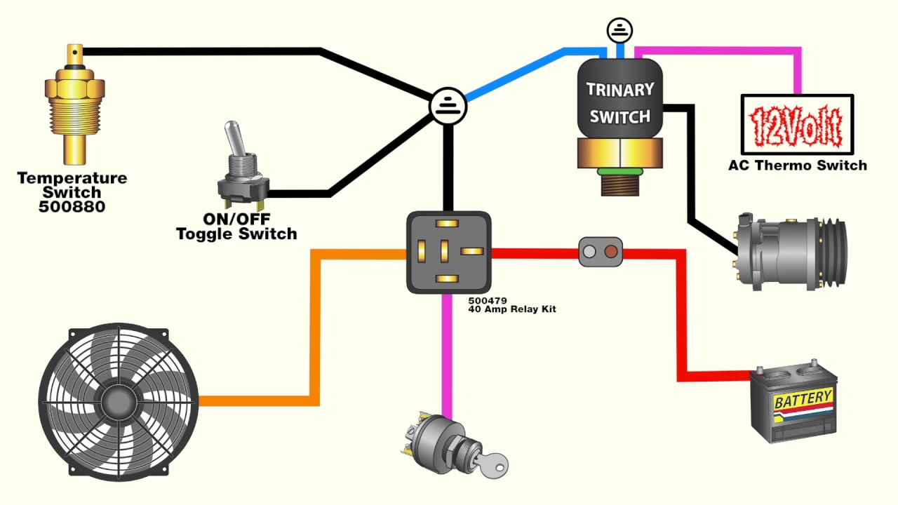
How To Wire An Electric Fan With An Ac Trinary Switch Youtube
